<<
Measurement of Electrical Power in Three-Phase Systems
Introduction
Three-phase systems are the backbone of power distribution networks in Europe and many other parts of the world, especially for industrial applications where they efficiently transmit high powers. These systems utilize three alternating current sources that are phase-shifted by 120° to each other to ensure continuous and reliable power delivery. For technicians, understanding the measurement and interpretation of electrical power in these systems is crucial, especially when dealing with complex loads.
Fundamentals
Phase Relationship
In a three-phase system, the three phases (L1, L2, L3) are each phase-shifted by 120° to one another. This leads to efficient utilization of conductor cross-sections and enables constant power transmission.
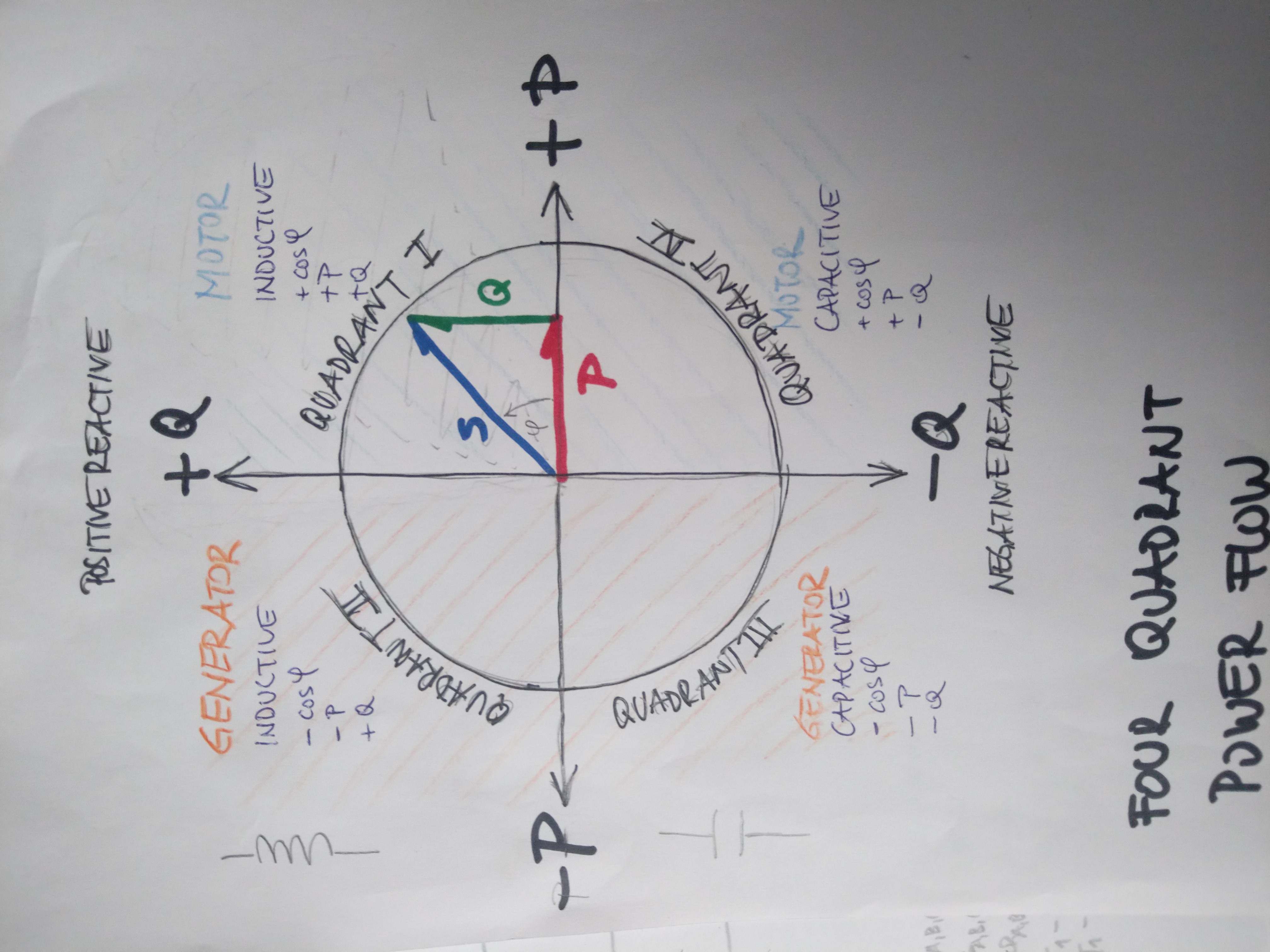
Four-Quadrant System
The four-quadrant system is used to analyze power in systems with variable loads and directions. It considers both the direction of energy flow and the type of load (capacitive or inductive):
Quadrant 1: Positive active and reactive power (consumer with inductive load)
Quadrant 2: Negative active and positive reactive power (generation, inductive load)
Quadrant 3: Negative active and reactive power (generation, capacitive load)
Quadrant 4: Positive active and negative reactive power (consumer, capacitive load)
Advanced Theoretical Foundations
Complex Power (S): Complex power is represented as a complex quantity and is the total power transferred in a three-phase system. It consists of both real power (P) and reactive power (Q), with the real part representing the actual power consumed or generated by the load, and the imaginary part representing the reactive power exchanged between the system and the load's inductive or capacitive elements. Mathematically, complex power is expressed as S = P + jQ, where j represents the imaginary unit and Q is the reactive power.
S = P + jQ = Vrms ⋅ Irms ⋅ ejφ
Where:
P is the real power in watts (W),
Q is the reactive power in volt-amperes reactive (Var),
Vrms and Irms are the root mean square values of voltage and current,
ejφ represents the phase angle φ between current and voltage.
Real Power (P): The real power in a three-phase system, without considering the power factor, can be simplified for balanced loads as:
P = √3 ⋅ VLL ⋅ I ⋅ cos(φ)
Where VLL is the line-to-line voltage and I is the line current.
Reactive Power (Q): The total reactive power for balanced loads in the system is calculated by:
Q = √3 ⋅ VLL ⋅ I ⋅ sin(φ)
Apparent Power (S): Apparent power is the magnitude of the complex power and represents the total power flow in the system, regardless of whether it is real (active) or reactive power. It is the combination of real and reactive power and is measured in volt-amperes (VA) or kilovolt-amperes (kVA). Apparent power reflects the total capacity of the system to deliver power to the load, considering both active and reactive components. Mathematically, apparent power is calculated as the square root of the sum of the squares of real and reactive power
S = √(P2 + Q2)
Power Factor (PF): The power factor, the ratio of real power to apparent power, is determined by:
PF = P/S = cos(φ)
Recommended resources
Electrical and Electronic Engineering for Mechanical and Process Engineers by Rolf Fischer. This book provides a solid introduction to the fundamentals of electrical engineering, including three-phase systems and power measurements.
Electrical Engineering: Principles & Applications by Allan R. Hambley. This textbook is another excellent work that covers the fundamentals of electrical engineering, including three-phase systems.
Grundlagen Wechsel-/Drehstrom von Michael Peppel und Wolf-Rainer Novender
Introduction to Complex numbers by Tony R. Kuphaldt
Phasor introduction and demo by Erik Cheever
Power System Analysis by John J. Grainger and William D. Stevenson. This book provides an in-depth treatment of power system analysis and discusses three-phase systems in detail.
For specific academic papers, IEEE Xplore and IET Digital Library are excellent sources, containing numerous articles and publications on electrical engineering and specifically on three-phase systems and power measurements.
IEEE Xplore Digital Library: An extensive collection of scientific articles and conference papers in the field of electrical engineering and electronics. Here you can find specific research papers on almost any topic in electrical engineering.
IET Digital Library: Another major resource for technical literature managed by The Institution of Engineering and Technology.
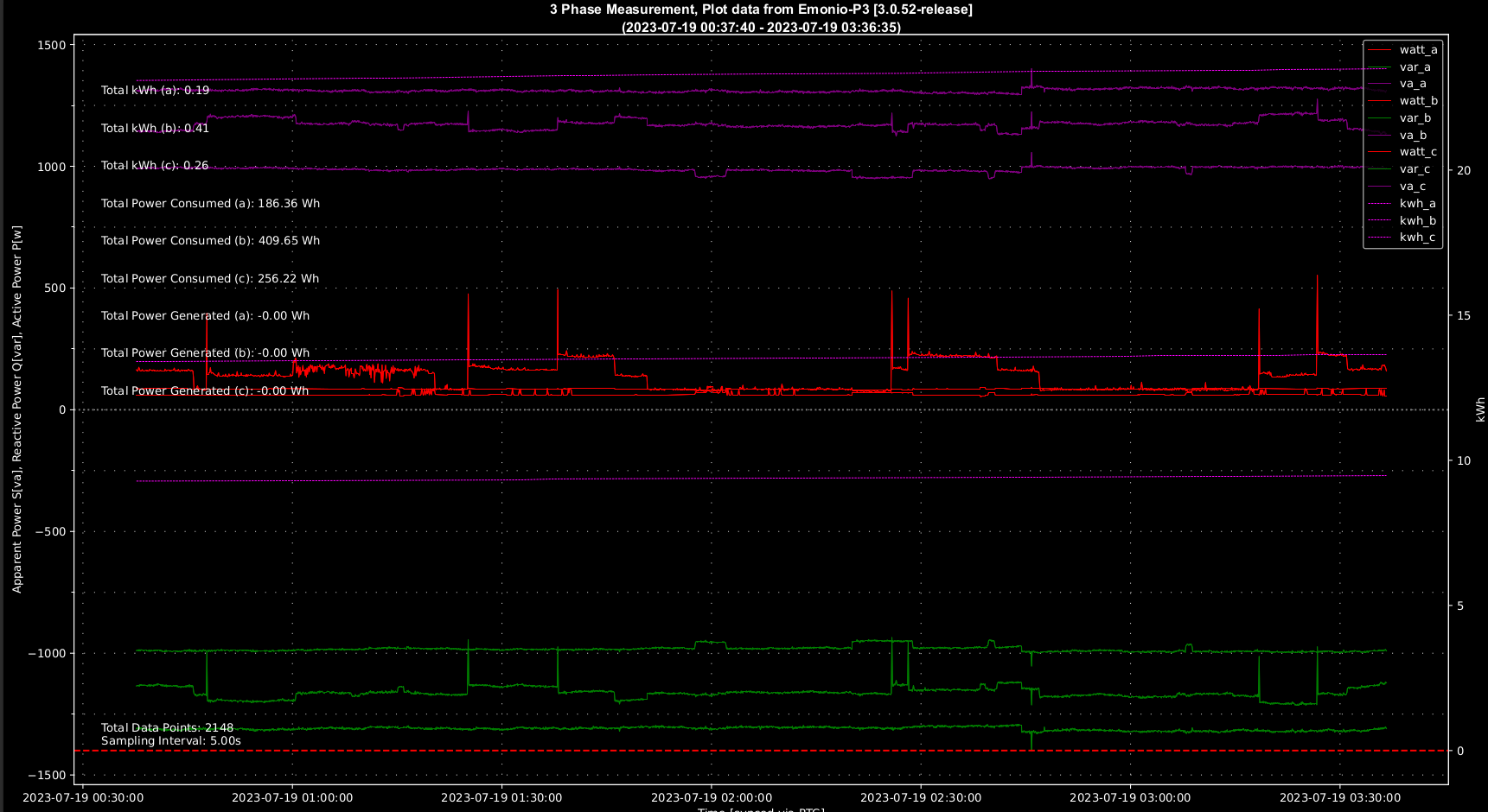
Measurement example from Live-Scenario
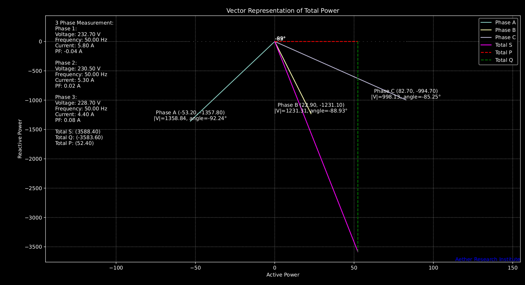
Vector diagrams are a graphical method used to represent the relationship between voltage, current, and power in three-phase systems. They provide a visual representation of the phase angles and magnitudes of these quantities, aiding in the analysis of power flow and system behavior.
Representation of Phasors: In a vector diagram, quantities such as voltage, current, and power are represented by phasors, which are vectors rotating in a complex plane. The length of the vector represents the magnitude of the quantity, and the angle with respect to a reference axis represents the phase angle.
Power in a three-phase system is the vector sum of the real and reactive power components. The power phasor diagram shows the relationship between apparent power (S), real power (P), and reactive power (Q), providing insights into the power factor and power distribution in the system.
If you have proper data you can use our vector-plot tool to visualize P,Q and S vectors.
Doing correct measurements in electrical systems is not a simple task. We know how to calculate correct and accurate but we will always need equipment to help us reach our goal. Below are the devices listed which we use on a daily basis to do all kind of research in the electromagnetic spectrum.
RIGOL MSO5000 oscilloscopes with all kind of HF/HV probes, emonio P3 measurement devices, RS Pro S3 Multimeter and tons of other stuff. :)
to be continued...
v13032024